
P R O J E C T S
Spacecraft Preliminary Design DRRoP Project
Fall 2022 - Present
Spacecraft Preliminary Design exposes senior undergraduates to the conceptual and preliminary design of a system. At the end of the semester, we will have a design ready for manufacturing in the spring semester. For this project, we chose...
×
Spacecraft Preliminary Design exposes senior undergraduates to the conceptual and preliminary design of a system. At the end of the semester, we will have a design ready for manufacturing in the spring semester. For this project, we chose the NASA FLOATing DRAGON (Formulate, Lift, Observe, and Testing: Data Recovery and Guided On-board Node) Challenge. For this competition, we need to develop a preliminary prototype for a system to deliver a data vault to the ground in a safe and guided manner. Additional details for this competition can be found here.
Our project is called DRRoP (Dynamic Release and Recovery of Payload). We have currently just begun this project and are coming up with requirements and starting on trade studies, so I'll update this section with additional details as the semester goes on.
RDL Test Cell 4 Design Team
Winter 2020 - Spring 2022
The RDL (Rocket Development Lab) Test Cell 4 Design Team was working on creating a new rocket test cell for Embry-Riddle. This rocket test cell allowed us to raise a rocket from a horizontal to a vertical position via the use of I beams, a winch, and various support structures. Currently...
×
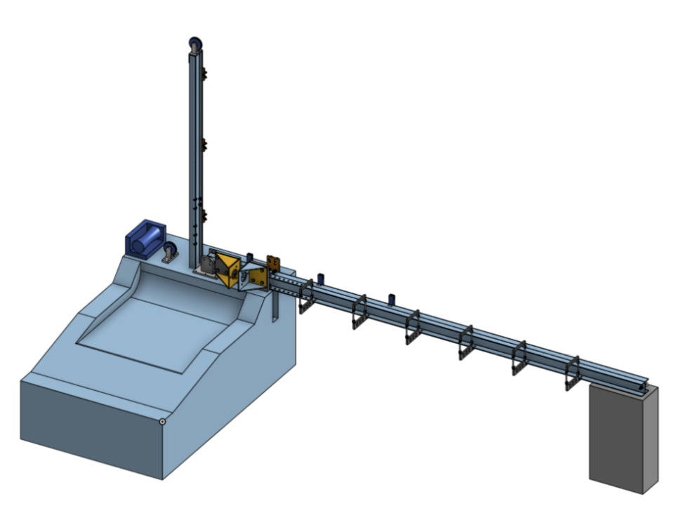
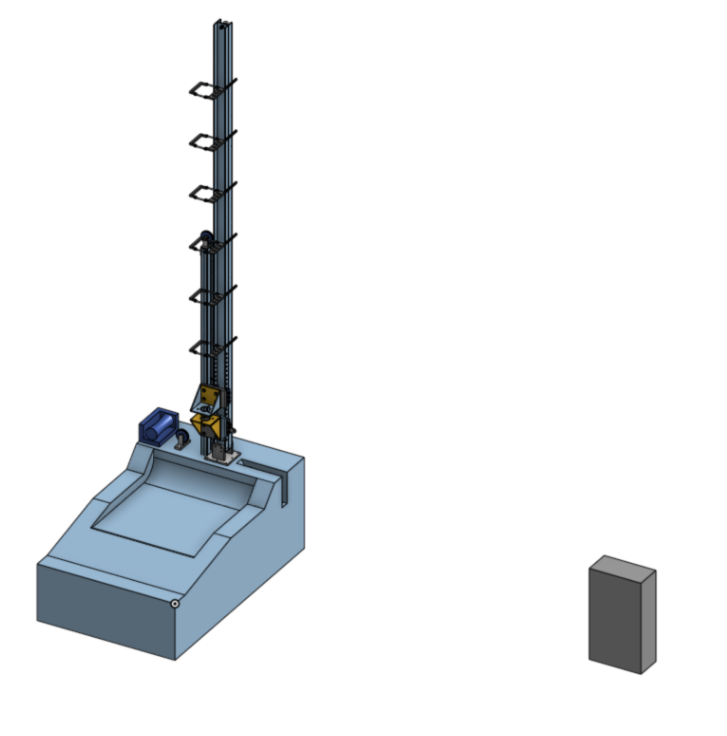
The RDL (Rocket Development Lab) Test Cell 4 Design Team created the design for a new rocket test cell for Embry-Riddle. This rocket test cell allows us to raise a rocket from a horizontal to a vertical position via the use of I beams, a winch, and various support structures. Currently, the project is on hiatus.
This project required the application of many soft and technical skills. We needed to have good communication skills to reach out to alumni, professors, and current students to figure out what type of test stand is needed. As our customer is the university, we needed to ask all the potential clients about what difficulties they have experienced testing on previous test cells and how we could design an improved test cell. One of our potential designs included the use of a piston, so I had to reach out to multiple vendors to gain specifications of potential pistons as well as compile potential piston specifications in a master list. Although, we aren't using the piston idea, this was still a valuable experience as I hadn't realized how many smaller things had to be done to create a design.
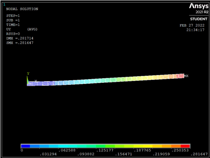
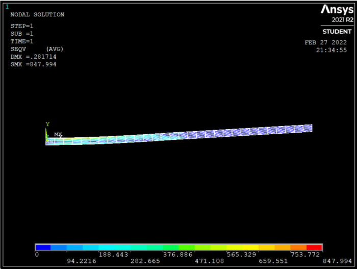
In terms of technical skills, we have had to apply a lot of curriculum that we have learned in dynamics, structures, and solid mechanics in order to gain rough estimates for forces and stresses involved. We have primarily used Matlab to solve various systems of equations to figure out what values the various brackets and pins can support. We have also done some idealized calculations via ANSYS. For example, the image below contains the Von Mises stresses and displacement experienced by the horizontal I beam if it is lifted at approximately the midway point.
A CAD model done by one of the members of my team can also be seen below. The first image is a CAD of TC4 in a horizontal position whereas the second image is TC4 in a vertical position.
This was a very challenging project since there was a lot of information that we didn't know or were just learning. By researching various other designs and reaching out to our sister campus in Daytona, we were able to create a final design and present it for approval in Spring 2022. Currently, the project is in hiatus as other projects in the RDL are prioritized. I will add more relevant details in the future.
Dots and Boxes- C++ Project
Fall 2020
Dots and Boxes was my final project for my C++ class. For this project, we had to incorporate what we had learned throughout the semester into a project of our choice. This included topics such as basic loops and functions, object oriented programming (classes, constructors, inheritance, operator overloading, object composition, etc.), and...
×
Dots and Boxes was my final project for my C++ class. For this project, we had to incorporate what we had learned throughout the semester into a project of our choice. This included topics such as basic loops and functions, object oriented programming (classes, constructors, inheritance, operator overloading, object composition, etc.), and other miscellaneous concepts (file IO, exceptions, UML diagrams, etc.).
In case you haven't heard of dots and boxes. Here is a wikipedia page explaining what it is.
How the program works
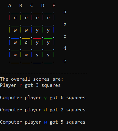
Classes were used to store the winner, human player, and computer player data such as how many boxes they have, what name they had, and what color their name was. The insertion operator was overloaded to print out all these values more easily.
Upon startup, depending on what gameboard size the user wanted, file IO was used to print a string array to represent the game board.
Then the user would enter an input. Loops and if statements were used to ensure if a valid input was received or not. Their input would also be checked against an integer array to ensure that they were not entering an input that had already been done.
For the computer player, the computer would choose a random spot to draw a line, but would prioritize picking a spot where it would form a box. Thus the computer player isn't truly random and you, as a player, would have to carefully pick your inputs as well.
The game would continue until all the boxes had been claimed and then would print the game results.
Here is a zip file containing my code if you would like to try it out and a pdf further explaining some parts of it. Do note that the header file was done incorrectly as it contains more than a header file should ideally have, however it still functions properly.
LEGO Lunabotics
Fall 2019
The LEGO Lunabotics project was done in my first semester as an undergraduate student. This project involved working in a team to create a robot out of legos that would simulate a robot picking up samples, traversing terrain, and then depositing the samples in a predetermined location. This project ...
×
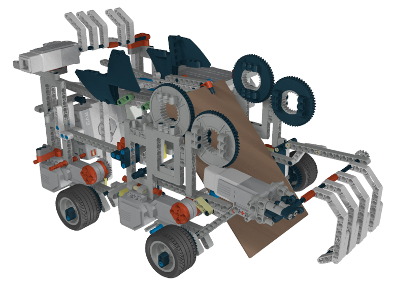
The LEGO Lunabotics project was done in my first semester as an undergraduate student. This project involved working in a team to create a robot out of legos that would simulate a robot picking up samples, traversing terrain, and then depositing the samples in a predetermined location. This project taught me a lot about working in a team, and how valuable input from other team members can be as well as how everyone plays an important role in a team project.
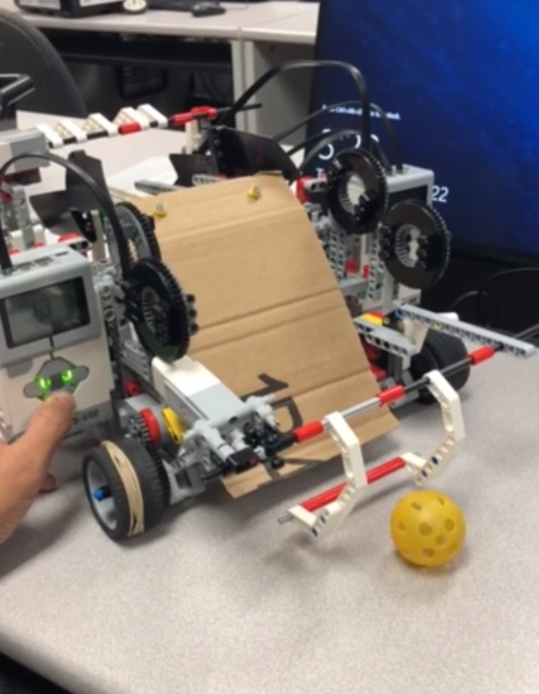
The objective of our rover was to navigate around an obstacle course (moving around previously placed balls without touching them), picking up golf and wiffle balls, moving over a ramp, and then depositing the balls in an elevated container.
We, as a team, brainstormed many potential ideas such as a crane, a scooper, an elevator; we finally decided to make a kicker. Here is a CAD model of our rover using the greatest CAD model software known to mankind, Leo CAD (A LEGO CAD software).
The idea of the rover was to kick the balls into the top part of the rover. And since the top part was elevated, there was a gate at the top which would open up and deposit the balls into the elevated containers.
This project was definitely very stressful due to time limitations. We had about 8 weeks to finish making a rover that would be capable of doing the tasks described above. This included a design PDR and CDR as well. We wasted the first 1 or 2 weeks not communicating effectively with each other as we felt too shy, so we weren't able to really get into designing a rover until week 3. As a result, we had to rush through our design and it felt much more stressful. This taught how valuable it is to effectively communicate with a team from the beginning. Two of our four members also dropped out later in the project as well. Thus, once again, we had to rush in our design and stick with one idea rather than making small modifications for a better design. Once again, communication from the start would have saved time later on in the project which could have been used to make a better design.
Vibration Prediction LSTM Undergraduate Research Project
Spring 2022 - Present
The beam vibration research project is a research project with Dr. Yabin Liao as well as another student. The goal of this research project is to create...
×
The beam vibration research project is a ongoing research project with Dr. Yabin Liao. The goal of this research project is to create a model of vibration for beams by using machine learning (LSTM model). This work is based upon some of the work Dr. Liao has done with previous students.
So far, I have done a multitude of tasks including, but not limited to, the following:
- Created ANSYS base excitation models of a model airplane wing and a rectangular beam
- Developed long short term memory (LSTM) neural networks in MATLAB and Tensorflow (Python) to predict the maximum deflection of the models at their tips
- Drafted models of the model airplane wing and rectangular beam in CATIA for submission to a machine shop for manufacturing
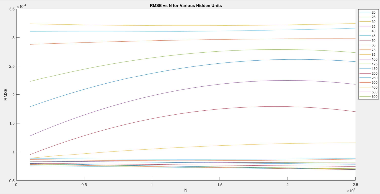
- Researched model parameters of LSTM models
Currently, we are awaiting for the parts to be manufactured, so we can run experimental tests on the models.
Some of the work I have done can be found below.
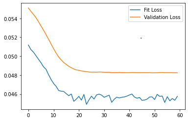
Below is an example of a LSTM loss graph. As a LSTM model trains, it generally should become more accurate over multiple iterations (lower loss). There are a variety of parameters that can be changed such as the type of layers used, the number of layers, the size of the hidden state, the shape of the input, the amount of epochs, etc. A lot of LSTM model optimization is train and error to find the model with the least loss. Generally, the goal of training a model is to lower the loss of a model to increase accuracy during predictions.
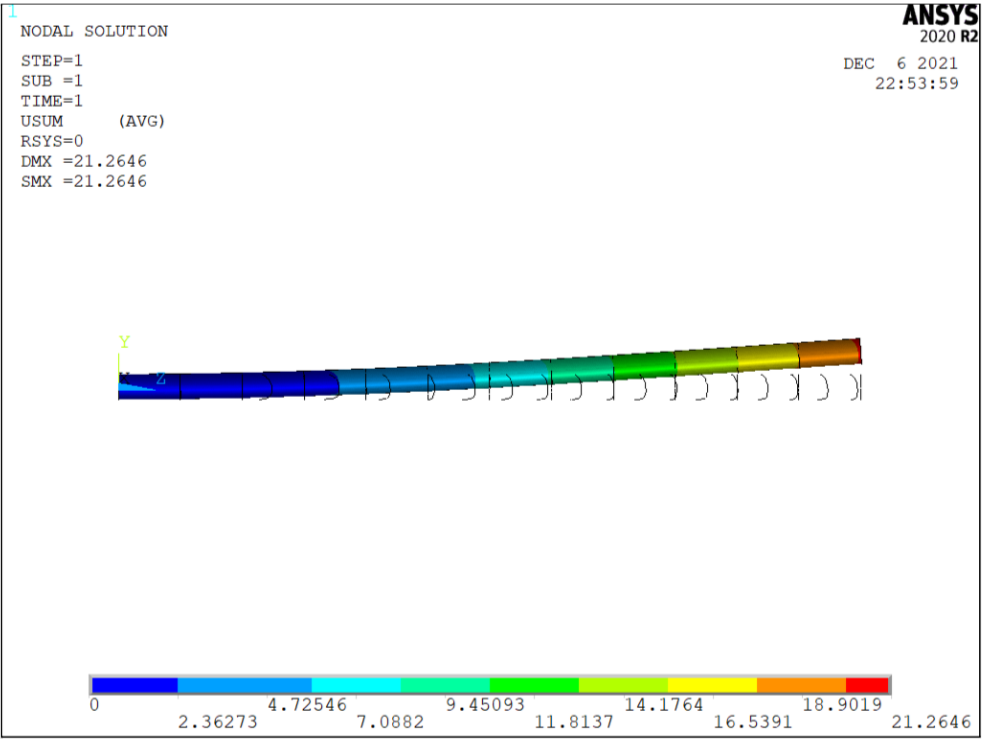
ANSYS is a very useful tool in determining the deformations experienced by an object. For our case, we subjected an object to random base vibration and measured what the response was towards the end of the model. The data from ANSYS was used to train LSTM models.
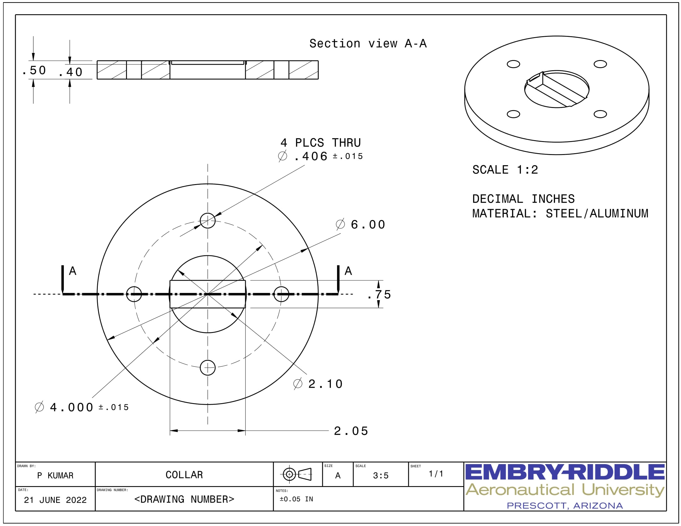
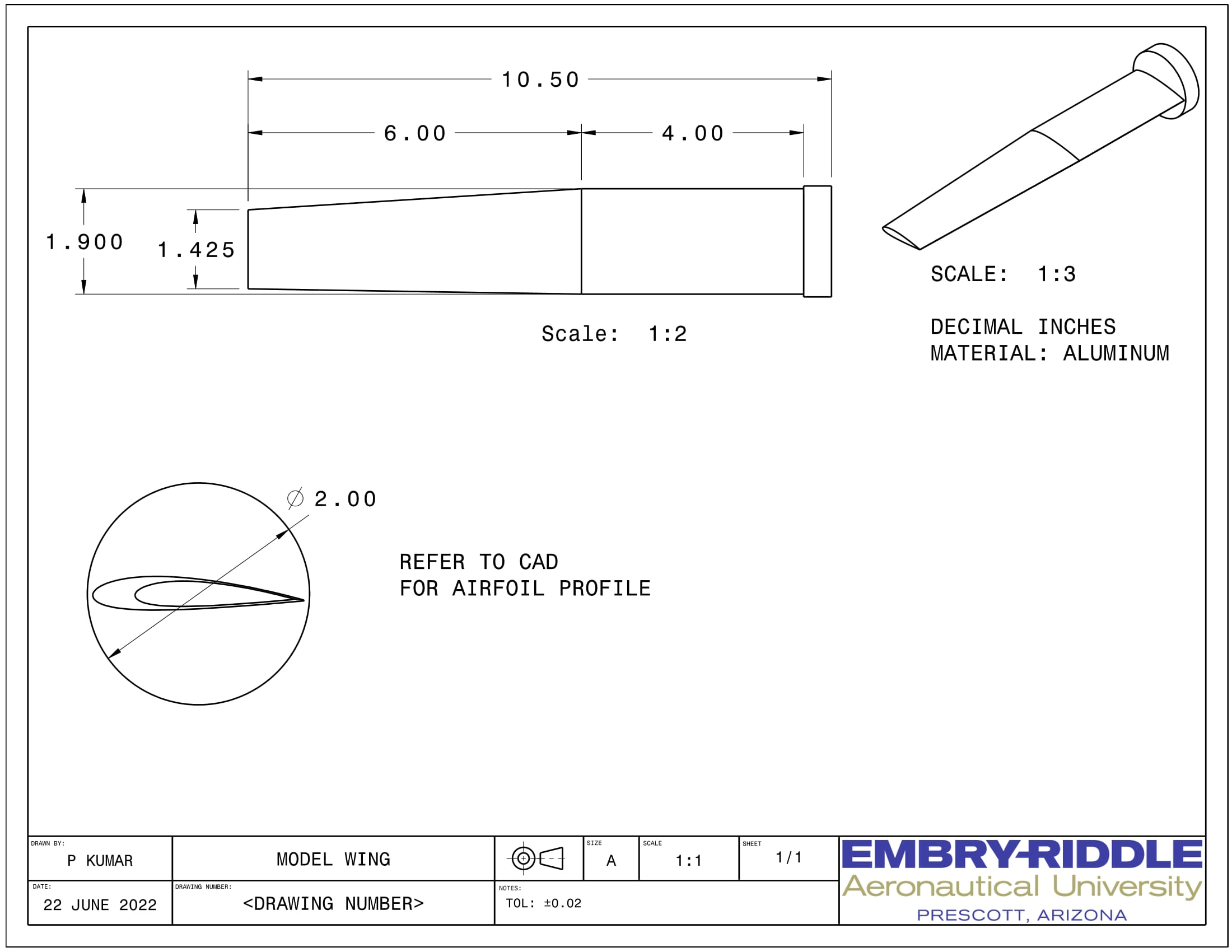
Based on the constraints posed by the shaker table and material we have access to, an airplane wing section was designed. Models of the airplane wing as well as the bracket to hold the model can be seen below.
The airplane wing model is currently being machined by the AXFAB machine shop at ERAU. We are also currently in the middle of testing new vibrometer software for the shaker table.
There is still a lot of work to still be done. We have also submitted a paper to the IMECE conference. I will include a link to it once it gets officially published. Additionally, I will be presenting at the IMECE conference in October to talk about what my team has accomplished so far.
ANSYS FEA Airplane Wing Project
Fall 2021
This project was my final project for my Aerospace Structures I class. We had to use ANSYS to build a finite element model of an airplane wing and ensure that the model fell within the main project parameters of...
×
This project was my final project for my Aerospace Structures I class. We had to use ANSYS to build a finite element model of an airplane wing and ensure that the model fell within the main project parameters of a maximum deflection at the wingtip of 20-24 in and ensuring that the 7075-T6 aluminum wing does not yield. Other design criteria included a yield strength of 75 kpsi, a FOS of 1.6, a maximum wing weight of 2300 lbf, a 6000 lbf tip load, and 40000 lbf of lift.
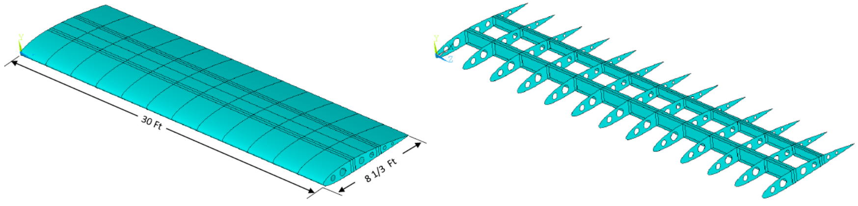
An image of the basic airplane wing can be found below:
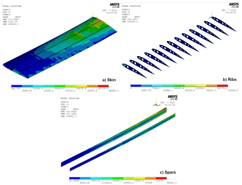
We were given a basic igs file of the airplane wing. Our primary task was to alter the thickness of the various parts of the wing to ensure that it was able to handle the given loads without experiencing too much stress or deformation. A lot of time was spent doing thickness adjustments, mesh refinements, and reiterating the stress calculations to narrow down the range of thickness for the airplane wing. Final images for the deflection and stress in the wings can be seen below.
As we had to use ANSYS APDL for this project, it became quite repetitive and frustrating at times when small mistakes were made, and they couldn't easily be undoed. The APDL interface was also a bit outdated and hard to navigate. Despite these challenges, it was still very fulfilling to be able to visually see the displace and stresses of the airplane wing
RDL Ablatives Group 2
Fall 2020
The RDL Ablatives Group 2 Team sought to research materials that would best absorb heat from a rocket engines. Ablatives are sacrificial materials that protect vehicles, rocket nozzles, etc. from heat. The Ablatives Team didn't exactly seek to find an sacrificial material to act as an ablative, but rather, we searched for an additive to add to epoxy which would...
×
![]()
The RDL Ablatives Group 2 Team sought to research materials that would best absorb heat from a rocket engines. Ablatives are sacrificial materials that protect vehicles, rocket nozzles, etc. from heat. The Ablatives Team didn't exactly seek to find an sacrificial material to act as an ablative, but rather, we searched for an additive to add to epoxy which would increase the melting temperature of the epoxy.
There are many test chambers in the RDL, and many of them consist of silica tape. This silica tape is first covered with epoxy and then wrapped around a mold. When these test articles are tested, the heat from the rocket engine causes the epoxy to melt and therefore, the test article unravels. Our goal was to find an additive to the epoxy which would ultimately allow the test article to endure heat for a longer period of time.
Our Process
I'll describe the general process for testing our samples or in RDL lingo - coupons. Due to documentation problems (us not taking enough photos), I have combined the photos from our two tests to help describe the procedure on how we tested our coupons.
We always start off by doing some general research into good potential additives to use based on a high specific heat capacity and chemical stability of the additive. For our first test, we tested graphite, glass, and a carbon fiber additive as those additives had been previously tested, but no good data was recorded. As no pure graphite was available, we had to use repurposed graphite as well (Taking pencils from the library and breaking them).
Based on data gathered from our first test, for the second test, we retested graphite, carbon fiber, and glass. We also added a new additive, an intumescent material. This material was made by one of the members by using flour and other kitchen ingredients which meant that you could eat it (and some of the members did!) We also used genuine graphite this time as well. We also increased the number of thermocouples from one to two per coupon for better data collection.
So moving onto the process...
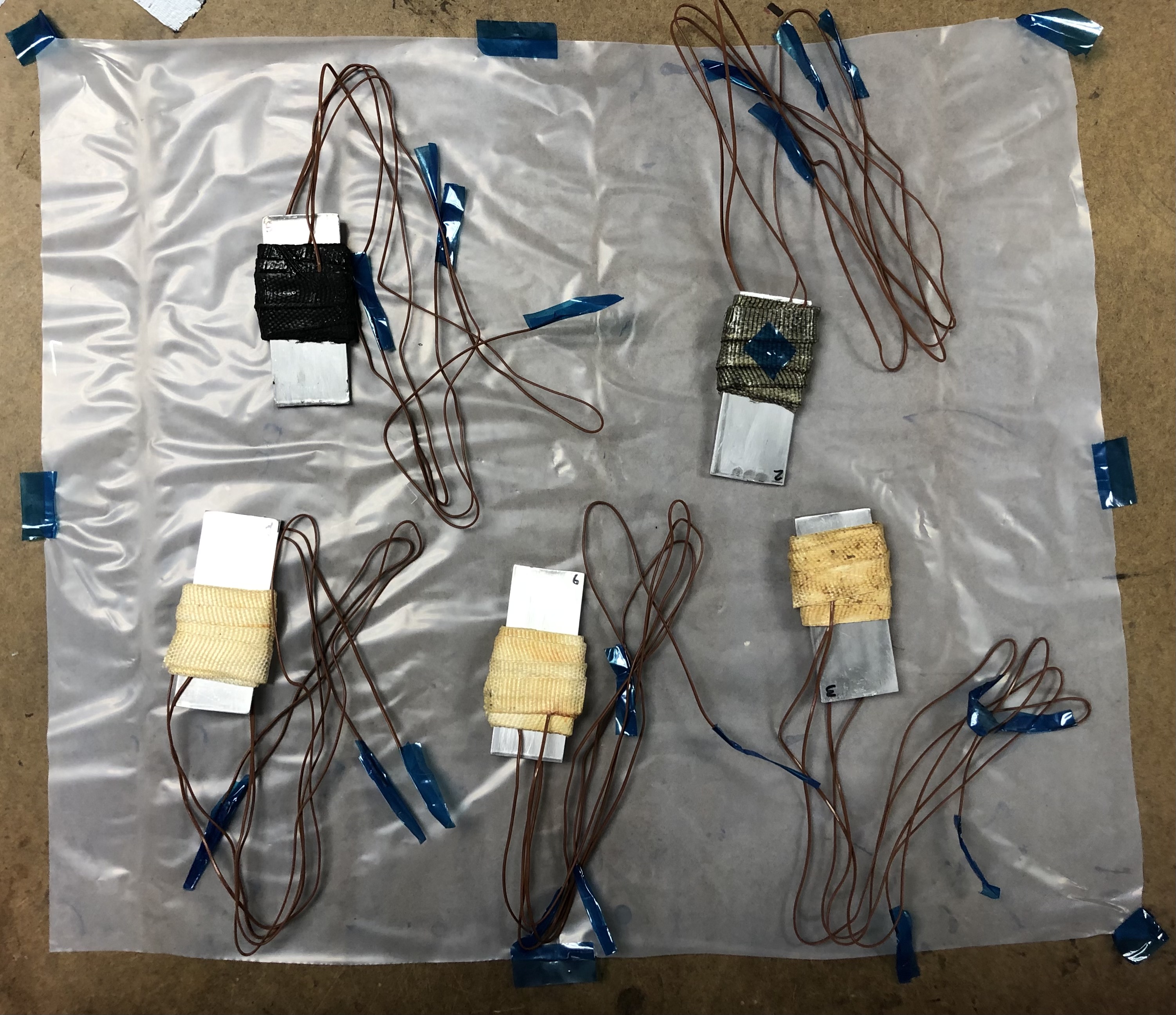
We would first prep our materials by cutting silica tape strips, measuring quantities of each additive, getting epoxy and hardener, and prepping the mandrels (aluminum rectangles). Unfortunately, we did not have pure graphite to use for our first test, so we had to resort to repurposing graphite from other sources as seen below.
Once the prep was ready, we could mix the epoxy, hardener, and additive together. Then, we would cover the silica tape with the goop. We would then wrap the silica tape around the mandrels as well as insert thermocouples.
The various mandrels would then be labeled to indicate what additive was added to the mixture. The mandrels were then vacuum sealed overnight to ensure that the silica tape was stuck together as much as possible.
Afterwards, the coupons undergo an oven cure cycle for multiple hours.
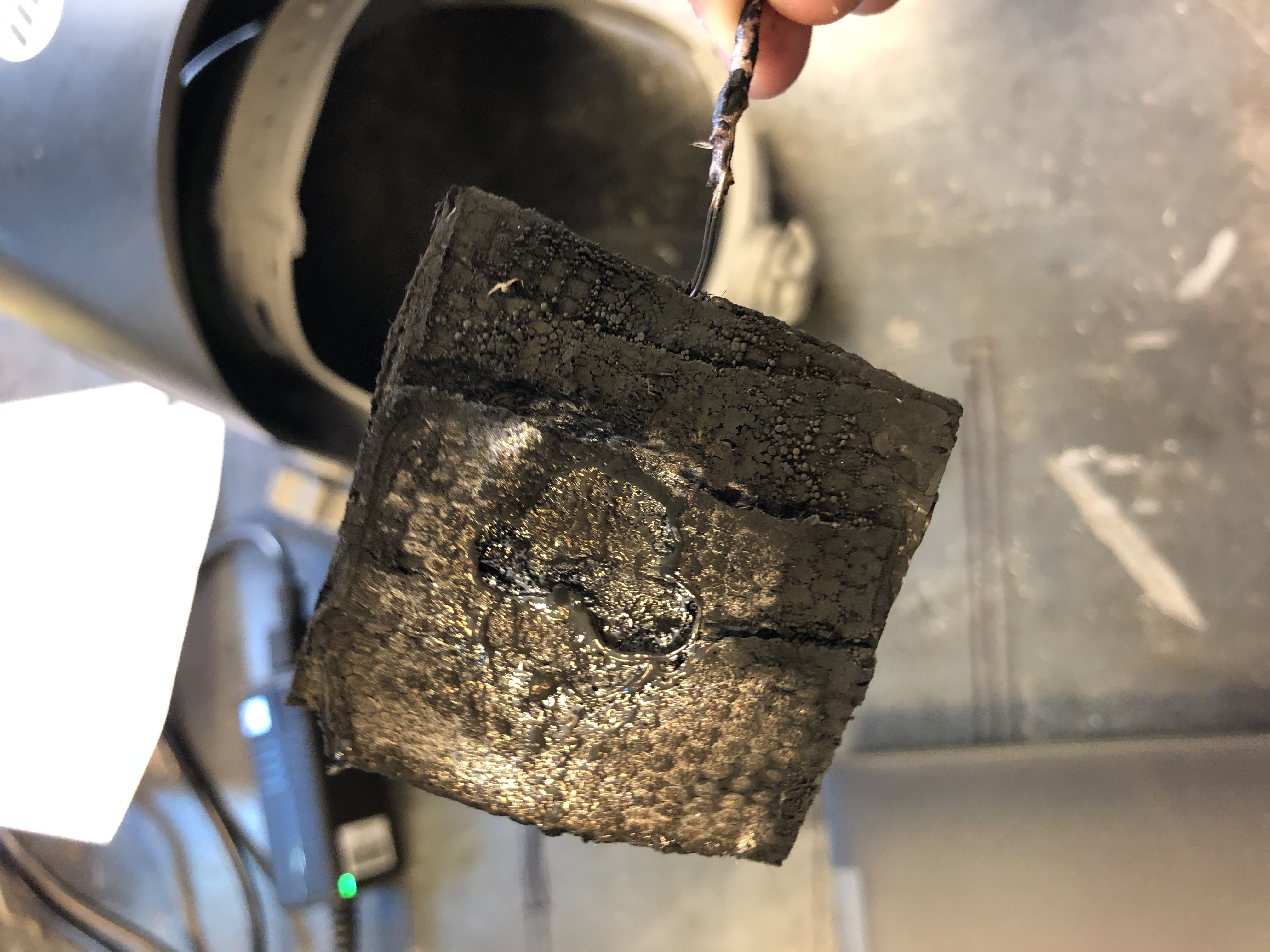
Finally, the coupons are removed from the mandrels via a process used quite often in percussive maintenance: beating it until it works. Or in this case, hitting the mandrels with a hammer or on the floor until the coupon is separated from the mandrel.
Each coupon that you see on the mandrel is cut in half, so we get two test coupons per mandrel. The thermocouples are then connected to a data acquisition module, so then they can be tested.
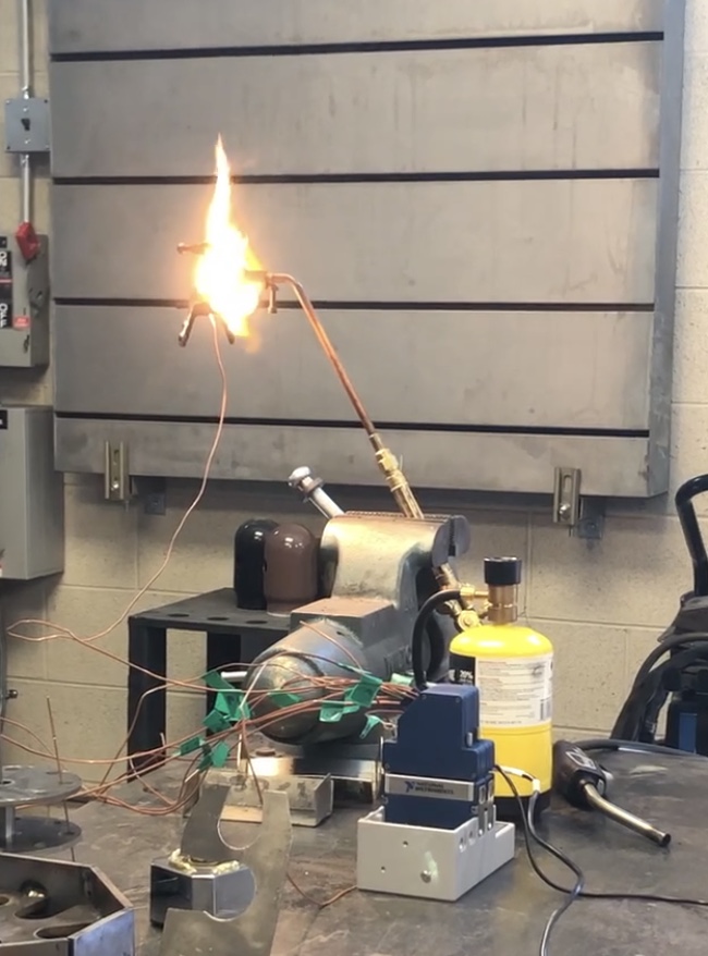
The max temperatures and the time it takes for the thermocouples to reach that temperature is recorded, so we can determine which additive best absorbed heat from the acetylene torch.
This is the general process for testing our coupons.
Overall, this was one of my first major projects involving a big team of people. It taught me about the value of being in a team where everyone can bounce their ideas off each other while doing something that everyone in the team has a passion for. It also involved us having to do research on things that we didn't learn in the classroom setting and made me realize that ultimately our college education is somewhat limiting, and there would be many things that I would have to learn on my own free time.
Aerospace and Astronomy Club
Fall 2018 - Spring 2019
In the Aerospace and Astronomy Club, I led students from 6th to 12th grade and helped them fly drones, construct model rockets, and taught them about physics and engineering skills with the help of...
×
In the Aerospace and Astronomy Club, I led students from 6th to 12th grade and helped them fly drones, construct model rockets, and taught them about physics and engineering skills with the help of Robert Woolley, a former navy pilot, and Aakash Joseph, a graduate of ERAU.
Since there were many young students in the club, we spent a lot of time answering various questions they may have and introducing them to various concepts they may be interested in such as drones, telescopes, engineering, rockets, and others.
This club included a lot of mini projects such as making model rockets, researching and compiling a list of drones to use in class, and learning how to use a telescope to look at celestial bodies.
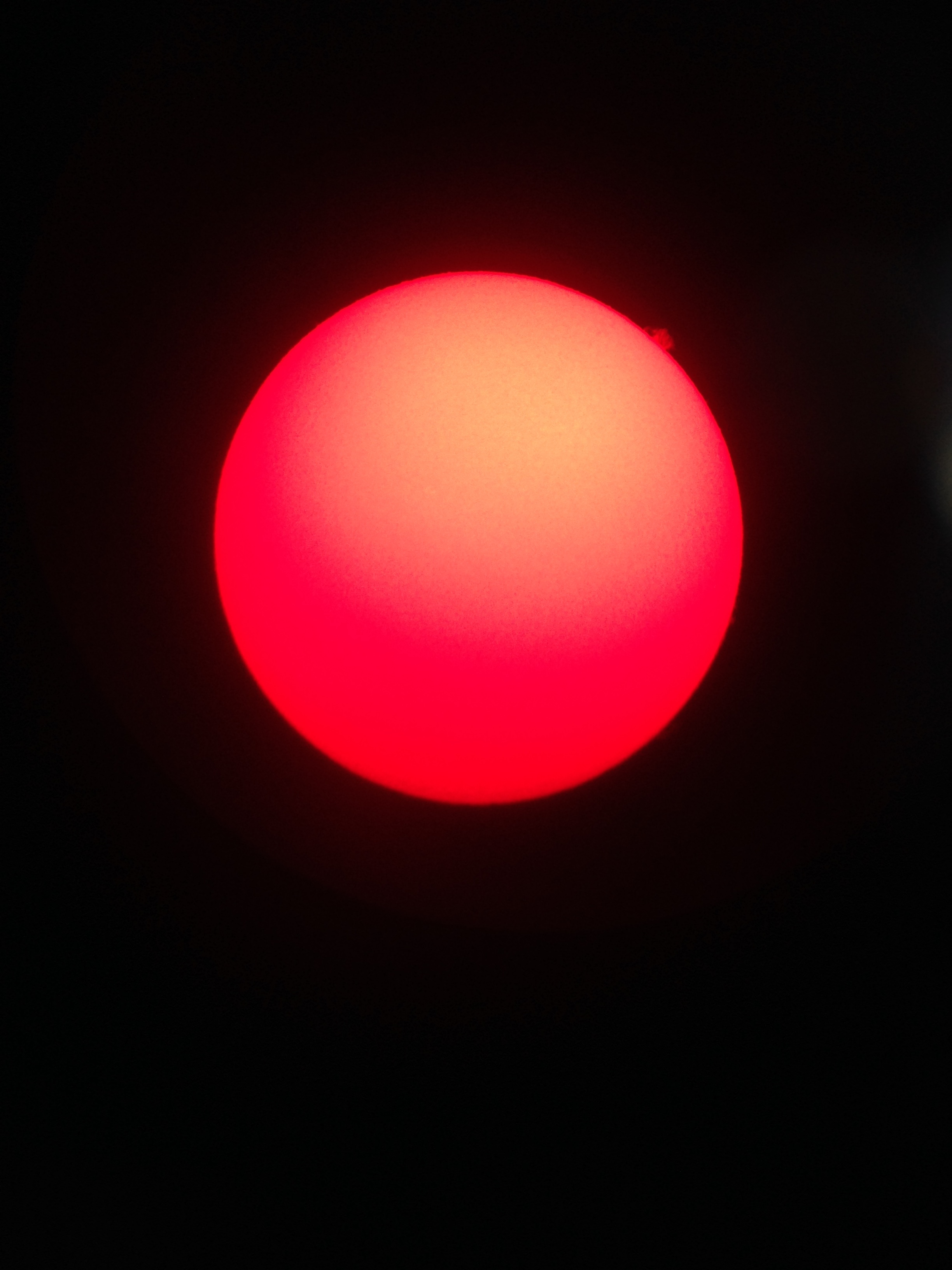
I wish I had more pictures other than this picture that I took of the sun through a telescope. If you click on the link, you can clearly see a solar prominence on the top right of the image. This solar prominence may seem small, but it's much bigger than the Earth! The reason the image looks reddish is because we had to use a hydrogen-alpha filter to highlight the sun's chromosphere. Generally, the sun is too bright to observe directly due to its photosphere (or "visible" surface). By blocking the photosphere with a hydrogen-alpha filter, it is much easier to observe the sun. This image is definitely one of my favorites.
The Aerospace and Astronomy Club was definitely one of the things that pushed me towards Aerospace Engineering as my major. I had been undecided as to what I wanted to pursue for the longest time, but hearing about Aerospace Engineering from the club advisors made me take a leap of faith and pursue AE as my major. The Aerospace and Astronomy Club also allowed me to improve my communication skills as I had to explain complex topics in a way that anyone from 6th-12th grade could understand it. It had to be simple enough for the younger members to understand, but also complex enough, so I wouldn't lose the interest of the older members. The Aerospace and Astronomy Club definitely played an integral role into the person that I was when I first entered college.
Space Systems Engineering Asteroid Mission Design Project
Spring 2022
For Space Systems Engineering, we had to design a mission to an Near-Earth asteroid (NEA) to test for its potential for in-situ resource utilization (ISRU). I was one of the team leads for my group. My team picked...
×
For Space Systems Engineering, we had to design a mission to an Near-Earth asteroid (NEA) to test for its potential for in-situ resource utilization (ISRU). I was one of the team leads for my group. My team picked Orpheus 3361 as our target asteroid. As a part of this mission, we had a spacecraft and a lander. The spacecraft, Eurydice, was responsible for COMMUNICATION STUFF and the lander, HADES, was responsible for mining of the asteroid to access for its potential for ISRU.
Overall, this project presented many challenges, and felt overwhelming from day one. Our first main goal was to determine the prime candidate for this mission. As we had to select a NEA, our primary challenge was determining the best asteroid with ISRU potential as NEAs lacked ice. Ice can be used for creating fuel as it can be split into oxygen and hydrogen. Thus, we had to shift focus into other ways to utilize an asteroid for ISRU. We realized that minerals on an asteroid could be used to create scrap metal for repairing purposes. Orpheus 3361 was finally chosen after much discussion about a variety of factors such as its spectral composition, distance form Earth, orbital period, and more.
There were many challenges faced along the way especially with managing a team and meeting various deadlines along the way.
You can find our final report attached below:
>
Fluids Course Model Rocket Project
Fall 2021
The model rocket project was my final project for my fluids class. It required us to apply the information we learned in fluids to land a model rocket inside a target zone. My team had to construct a model rocket based on a kit, simulate its trajectory, and...
×
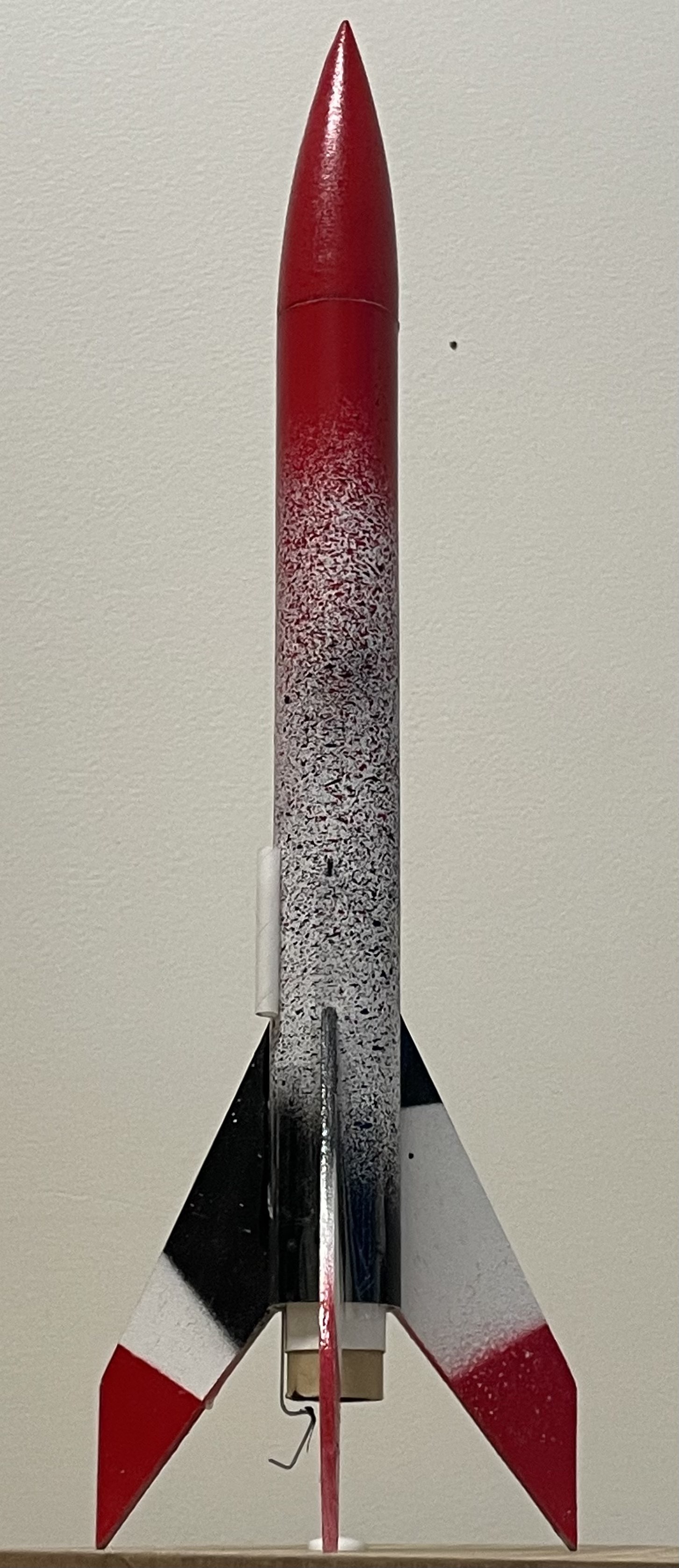
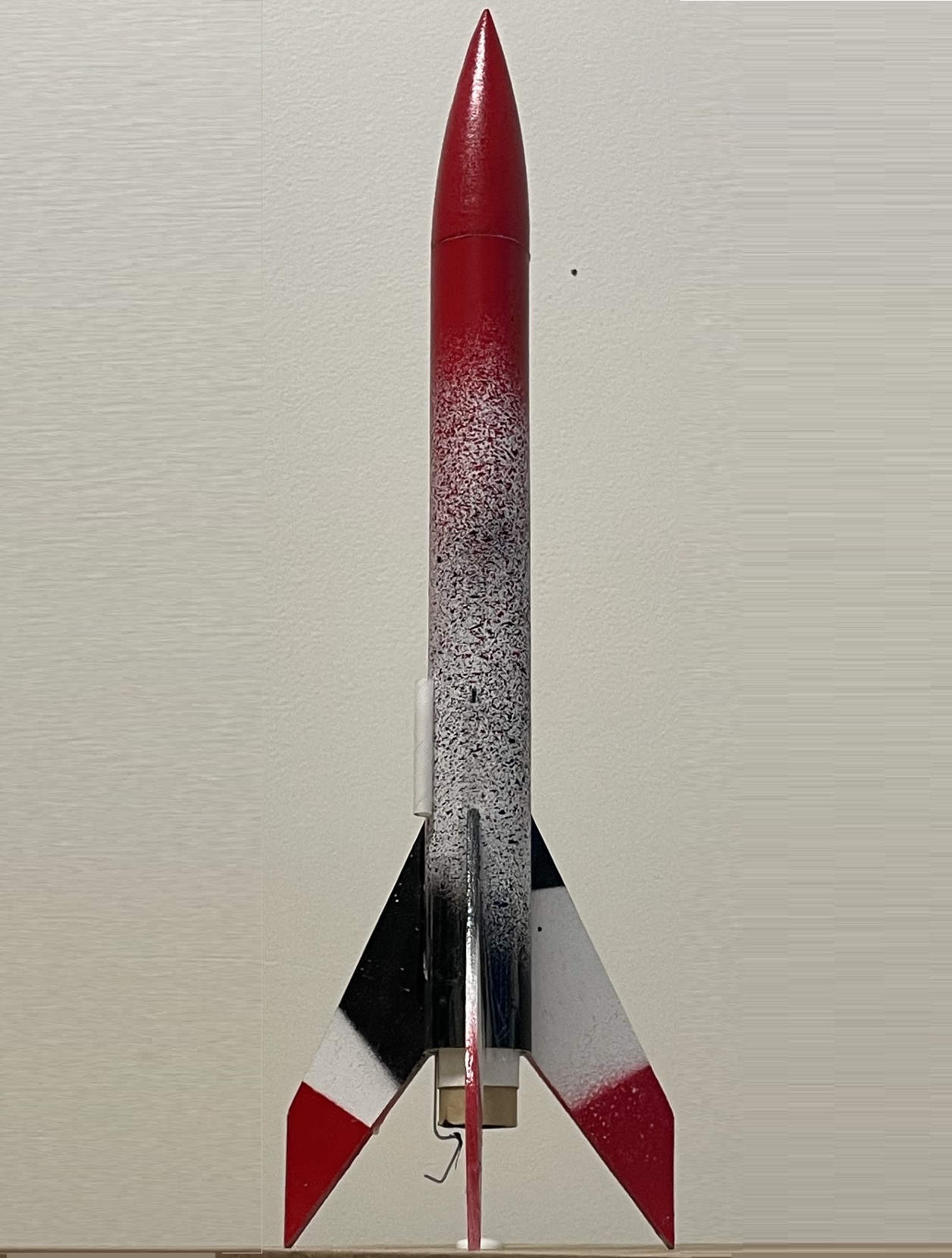
The model rocket project was my final project for my fluids class. It required us to apply the information we learned in fluids to land a model rocket inside a target zone. My team had to construct a model rocket based on a kit, simulate its trajectory, and make modifications to ensure that its trajectory fit within the project requirements.
The primary requirements for the project were the following: maximum altitude of 150ft, land within a 5yds zone located 40 yds away, and to use the provided model rocket with an A8-3 Estes motor. I was in charge of doing any appropriate calculations to determine its trajectory as well as if any additional mass needed to be added to our rocket to ensure it flew within the project requirements. I had to primarily learn how to implement thrust curves into Matlab via piecewise functions and how to do OpenRocket simulations. An image of our fully assembled rocket can be seen below.
Our code predicted a launch distance of 46.54 yds whereas our rocket landed 46 yds away. We used a launch angle of 72° and decided to slightly overshoot the rocket due to any unaccounted drag such as the rough paint finish.
Although this was a relatively simple project, it was still interesting to visually see the OpenRocket simulation, the Matlab code simulation, and the real life launch matched trajectories.
RDL Model Rocket Group
Fall 2019 - Spring 2020
In the RDL Model Rocket Group, we learned about the basics of rocketry as well as started to construct a model rocket. Unfortunately due to the COVID-19 pandemic, we were unable to finish the rocket and test it, however I did get the chance to...
×
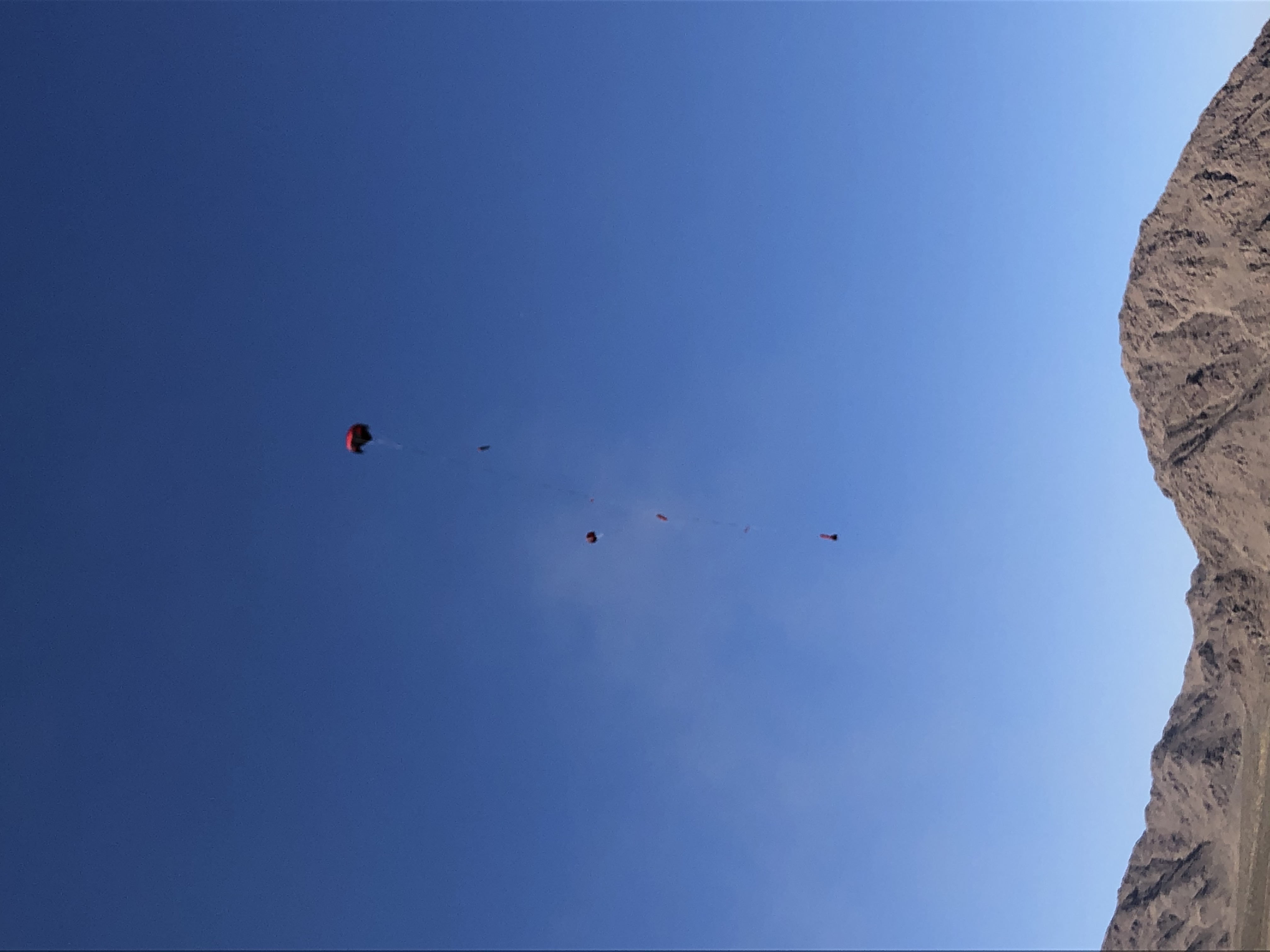
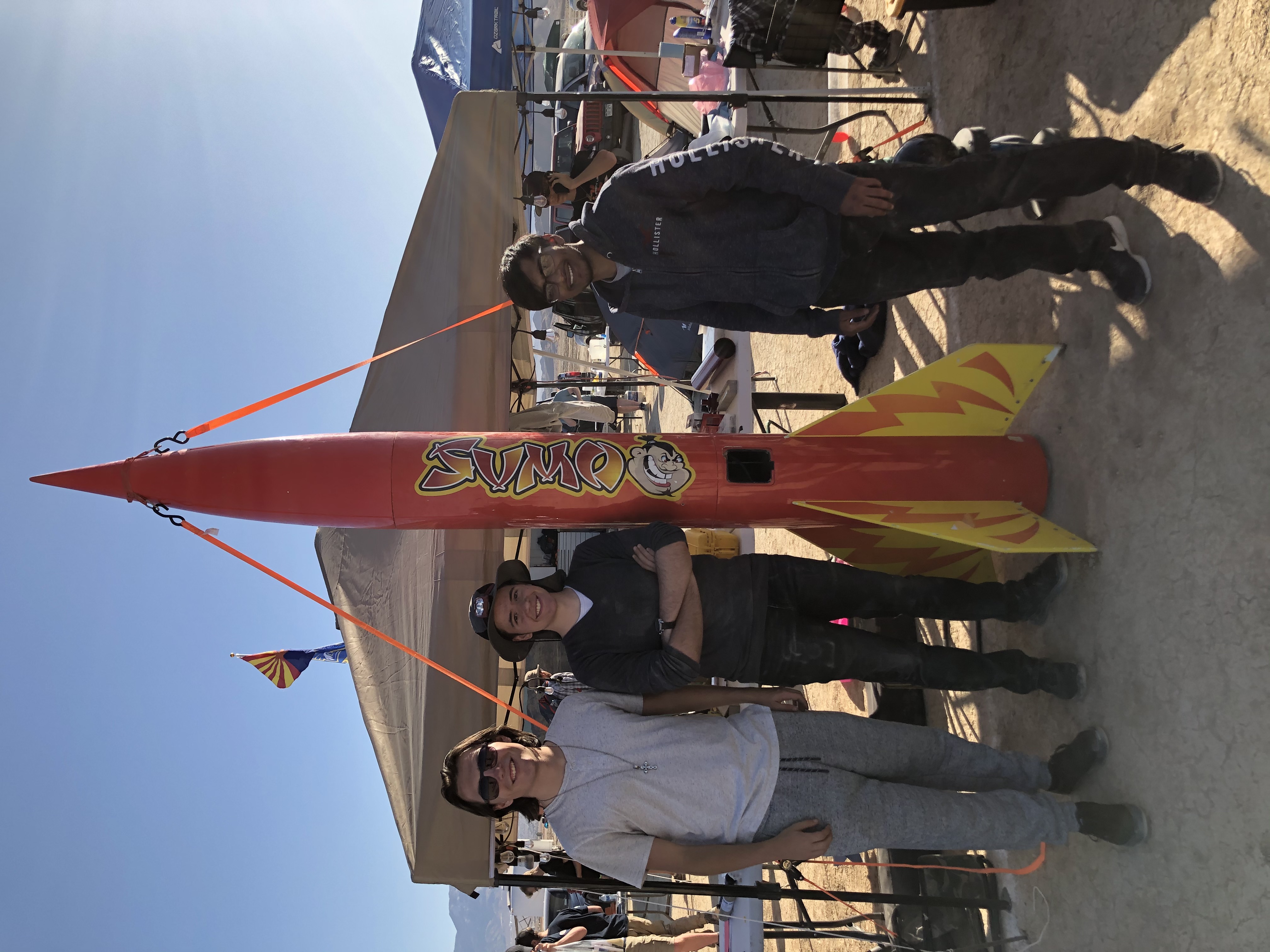
In the RDL Model Rocket Group, we learned about the basics of rocketry as well as started to construct a model rocket. Unfortunately due to the COVID-19 pandemic, we were unable to finish the rocket and test it, however I did get the chance to visit rocket launches at ROCstock in Lucerne Valley, California.
I unfortunately was unable to get any pictures of the model rocket we made since we were told in the middle of our spring break to not return due to the COVID pandemic. Thus, we were unable to finish our rocket, and I am not entirely sure what ended up happening to it either. I did get some really cool videos and pictures from ROCstock though. This group was essentially my first big introduction to rocketry as my main previous experience had been just making model rockets for 2 weeks during the Aerospace and Astronomy Club in high school. I also had never been to a launch site like this one before, so it was really cool to see so many people come together in one place to express their passion about rocketry.
Introduction to Special Relativity
Fall 2018 - Spring 2019
Introduction to Special Relativity was my senior project at BASIS Phoenix. For this project, I worked with Dr. Michele Zanolin at ERAU on dissecting and deriving the basics of Einstein's theory of relativity in a manner which high school students could understand. As a part of this project...
×
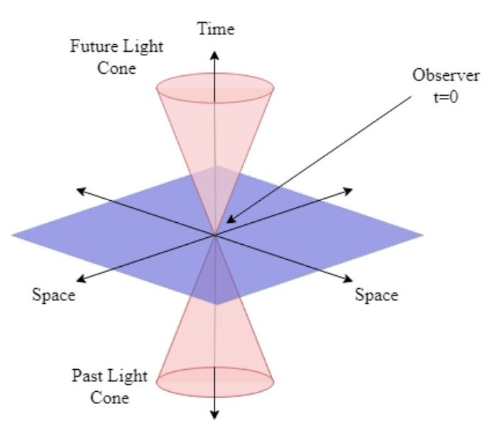
Introduction to Special Relativity was my senior project at BASIS Phoenix. For this project, I worked with Dr. Michele Zanolin at ERAU on dissecting and deriving the basics of Einstein's theory of relativity in a manner which high school students could understand. As a part of this project, I got the opportunity to sit in during project discussion meetings, meet many people working on projects similar to LIGO (Laser Interferometer Gravitational-Wave Observatory), and break down the fundamentals of the theory of relativity.
This project was my first experience with college since I got to meet many students and ask what college is like. As they were also students, conversations with them felt much more open. I also spent a lot of time with Dr. Zanolin in his office and learned about how different learning in college is compared to high school. College felt like it placed more emphasis on learning outside of a classroom setting and having to hold yourself more accountable.
The final product of my project was to create an introduction to special relativity based on Bernard Schutz's A First Course in General Relativity: Second Edition. A copy of the pdf can be found at the end of this text. I spent an incredible amount of time deriving various concepts and equations with Dr. Zanolin as well as working with his students to get a better grasp of the material. Most of the time visiting him was spent deriving concepts and time at home was spent learning LaTeX and typing up whatever I learned. This was a very valuable project in introducing me to what I could expect in college.
Click here for a copy of An Introduction to Special Relativity